

Caliper Cover, Gasket & Plate: Faults, Replacement, Care
Learn how caliper cover, gasket and plate faults develop on air disc brakes, how to diagnose leaks, replace the group correctly and extend its life.
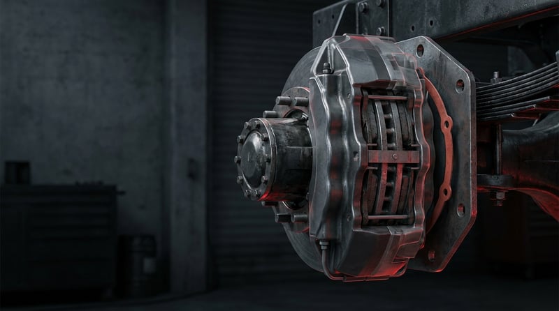
On a heavy commercial vehicle, a brake caliper fault usually arrives at the workshop described as "the caliper is finished", yet once the unit is stripped in the field most of the trouble turns out to sit not outside the caliper but underneath its rear cover. A handful of water that has worked its way inside, a gasket that has lost its shape or a plate with a crushed corner can jam the adjustment mechanism within a few thousand kilometres and wear the pad on one side only. Written from the perspective of a workshop foreman and a brake technician, this guide explains what the caliper cover, gasket and plate group actually does, how it fails, the correct diagnostic sequence, the discipline required when removing and refitting it, and the maintenance habits that extend its service life.
This document has been prepared by the VADEN technical team on the basis of heavy commercial vehicle disc brake service practice and OE manufacturer documentation. The values given here are general reference figures; for exact data such as tightening torque, clearance tolerance and service interval, the current OE service manual matching the vehicle's engine/chassis code takes precedence. Last updated: July 2026.
What Is the Caliper Cover, Gasket & Plate? Function and Operating Principle
The Caliper Cover, Gasket & Plate is a service group made up of the cover that isolates the internal mechanism of a heavy commercial vehicle disc brake caliper from water, salt and dust, the gasket that seals the joint between cover and housing, and the plate that spreads the clamping force from the piston/tappet across the back of the brake pad. It works at a typical actuator pressure of 6–8.5 bar and is generally renewed once every 2–4 pad sets.
On a modern heavy commercial vehicle the brake caliper is a floating mechanism that multiplies the thrust arriving from the actuator (brake chamber) through a lever-and-eccentric arrangement and transfers it to the pad through two tappets. The whole assembly runs inside the caliper housing, in a closed, grease-filled volume. The cover group closes off exactly that volume. The cover is not merely a "blanking plate": it is the first and often the only barrier separating the adjuster spindle, the one-way adjuster gear and the grease pocket from the outside environment.
The cover cannot do the sealing job on its own. The gasket seated between cover and housing — depending on the application a flat paper/elastomer gasket, a profiled sealing ring or an O-ring — fills the micro-irregularities of the mating face and establishes permanent surface contact under bolt load. The most common field mistake is reusing the gasket while the cover itself is still sound; once an elastomer gasket has been compressed it is permanently deformed and will not deliver the same seal on a second assembly.
The plate, by contrast, sits on the force side. In designs where the tappet ends press directly onto the pad backing plate, the plate converts point contact into surface contact and distributes the load, reducing crushing of the pad backing, wear at the tappet tip and vibration-induced noise. In some OE designs the plate also acts as a guide that fixes the position of the pad in its carrier. In short, the cover protects the inside, the gasket makes that protection leak-tight, and the plate distributes the outside force evenly. Because each one determines the service life of the others, they are usually listed in the catalogue as a single repair group.
Which parts are included in the group?
- Mechanism cover (rear cover): the metal or composite cover that closes the rear opening of the caliper housing.
- Cover gasket / sealing ring: the static sealing element between cover and housing, mostly single-use.
- Thrust plate: the plate that distributes force between the tappet and the pad backing.
- Guide/intermediate plate: the thin plate that sets the position and clearance of the pad in its carrier.
- Adjuster spindle cap and plug: the small plug that closes the access point to the automatic adjustment mechanism.
- Tappet boot and retaining ring: the boot protecting the exposed part of the tappet, together with its retainer.
- Cover bolts / screws: generally torque-controlled and single-use in most applications.
- Spring rings, clips and circlips: the small fasteners holding the cover and boot in place.
In which OE caliper families does it appear?
On heavy commercial vehicles the geometry of the caliper cover, gasket and plate depends far less on the vehicle make than on the caliper family fitted to it. The families most frequently encountered in the field are the pneumatic disc brake calipers originating from Knorr-Bremse and Wabco; besides Mercedes-Benz, Volvo, MAN, DAF, Scania, Iveco and Renault Trucks tractor units, these families also appear on trailer axles such as BPW, SAF and Schmitz. The same tractor model may carry a different caliper family in different production years, and even between its front and rear axle. These names are given only as application examples; the correct part is identified not by a brand name but by the type label on the caliper housing and the OE number.
What effect does the cover group have on brake performance?
The cover group does not generate braking force directly, but it determines whether that force is delivered consistently. In a caliper that has taken in water, the adjustment mechanism corrodes; as the pad wears the mechanism can no longer take up the clearance, pedal travel increases and brake imbalance develops between the two wheels of the same axle. ECE R13, the binding framework for heavy commercial vehicle brake performance, defines axle-based brake balance and effectiveness requirements; loss of cover sealing is one of the silent reasons a vehicle drifts outside those requirements. On the static sealing side, general standards such as ISO 3601 are used as a reference for O-ring size and tolerance families. The applicable standard and material class may vary with the caliper family; exact data must be verified from the OE catalogue for the part.
| Caliper type / application | Cover design | Gasket type | Characteristic service note |
|---|---|---|---|
| Single-tappet pneumatic disc brake (tractor front axle) | One-piece metal mechanism cover | Profiled elastomer ring | Cover bolts torque-controlled, gasket single-use |
| Twin-tappet pneumatic disc brake (tractor rear axle) | Cover plus separate adjuster spindle plug | Flat gasket or O-ring | Both tappet boots renewed together |
| Trailer axle disc brake (BPW/SAF type installations) | Metal cover with corrosion-protective coating | Elastomer ring | Road salt effect pronounced, coating integrity critical |
| New-generation calipers with composite covers | Reinforced polymer cover | Sealing lip integrated into the cover | Excess torque cracks the cover, torque wrench essential |
| Older-generation vehicles with drum brakes | No cover group fitted | Not applicable | Adjustment mechanism external, different maintenance regime |
Caliper cover, gasket and plate parts look very much alike; a diameter or thickness difference of a few millimetres cannot be told apart by eye. Do not select the part by "vehicle model" alone: verify it by reading the type label on the caliper housing, the production year and, where possible, the OE number on the part you removed. A plate of the wrong thickness changes the pad clearance and locks the automatic adjustment mechanism in the wrong position from the very first application.
How do you recognise a Caliper Cover, Gasket & Plate fault?
Caliper Cover, Gasket & Plate faults rarely announce themselves with a sudden failure; they usually progress as a slow loss of sealing followed by a chain of secondary damage. Because most of the symptoms are filed under the heading "caliper fault", correct diagnosis starts with separating a problem in the cover group from a problem in the mechanism. The table below matches field symptoms with likely causes and the method used to confirm them.
| Symptom | Likely cause | Check / verification |
|---|---|---|
| Grease leak behind the caliper, a dirty ring mark around the cover | Gasket fatigued or crushed, cover bolt loosened | Clean around the cover and inspect again after 200–300 km; check bolt torque |
| One side of the pad noticeably more worn (one-sided wear) | Plate distorted or of the wrong thickness, uneven tappet clearance | Measure the pad thickness difference between the two tappets with a caliper gauge; check plate flatness on a surface plate |
| Pedal travel increasing over time, brakes biting late | Water/dirt ingress, automatic adjustment mechanism unable to take up clearance | Open the adjuster spindle plug and check that the mechanism turns freely; measure pad clearance |
| Metallic rattle when braking or squeal at low speed | Plate has developed play in its seat, clip/spring ring broken | Try moving the assembly by hand at the caliper without removing the wheel; visually check plate seating |
| Swelling, cracking or corrosion blistering on the cover | Cover coating damaged, moisture accumulated inside | Surface inspection without removing the cover; look for water/emulsion in the internal volume during removal |
| The two wheels on the same axle heating up differently | Mechanism stiff in one caliper, brake dragging | Measure the axle-based temperature difference with a non-contact thermometer after a road run |
| Tappet boot torn, rust marks at its tip | Boot aged or not fully seated during assembly | Squeeze the boot by hand to look for tears; clean the tappet tip and inspect the surface |
| Uneven wear returning shortly after new pads are fitted | Old plate reused or caliper guides seized | Measure the free movement of the caliper on its guides; compare plate thickness against a new part |
Visual and hands-on preliminary diagnosis
The first step of diagnosis can be carried out without lifting the vehicle. A dark, oily, dust-laden ring in the rear area of the caliper is almost always gasket-related; on a pneumatic disc brake caliper, which contains no brake fluid, the only fluid that can escape is the mechanism grease. The most common field pattern is that the leak is deferred because it looks "minor" and the mechanism turns up seized a few months later. Flexing that can be felt when the cover surface is pressed with a finger, or coating that lifts easily with a fingernail, indicates that the cover needs to be renewed as well.
Confirming by measurement: pad clearance and thickness difference
The second step is measurement. The thickness of the two pads in the same caliper is measured separately with a caliper gauge; a clear difference means force distribution has been disturbed and suspicion points directly at the plate and the tappet clearance. Total clearance between pad and disc is specified by the manufacturer within a narrow band, and a value above that band is the clearest indication that the automatic adjustment mechanism is no longer working. The measurement result must always be compared with the figure in the vehicle's own service manual.
Internal volume inspection after removal
The third and most conclusive step is removing the cover. Once the cover is off, the colour and consistency of the grease inside is a diagnostic report in itself: if the grease is light and homogeneous, sealing has been maintained; if a milky-coffee coloured emulsion is visible, water has entered; a black, dry and grainy structure means the grease is thermally exhausted and has lost its protective quality. Wherever emulsion or rust marks are seen, the entire cover group — cover, gasket, plate, boot and fasteners — is renewed; the leaking part alone is not replaced.
How is the Caliper Cover, Gasket & Plate replaced? Step by step
Replacing the Caliper Cover, Gasket & Plate is an operation that requires the vehicle's brake system to be depressurised and made safe. The steps below describe a general service flow; the sequence and torque figures vary with the caliper family, and the vehicle's current OE service manual takes precedence.
Before working on the brake system, secure the vehicle on level, solid ground, chock the wheels, drain the air reservoir by the method described by the manufacturer and mechanically release the spring brake chamber. A pressurised chamber or a loaded spring releases sudden, heavy force during removal. Safety glasses, cut-resistant gloves and steel-toe footwear are mandatory; brake dust must not be inhaled, and extraction or wet cleaning must be used instead of a dry brush.
1. Secure the vehicle and depressurise the system: fit chocks, raise the vehicle onto stands, bleed off air pressure in the order described by the manufacturer and mechanically release the spring brake chamber.
2. Remove the wheel and clean the area: take off the rim, remove dust from around the caliper using extraction or wet methods rather than compressed air, and clean the heads of the bolts to be removed.
3. Record the pre-removal measurements: measure and note the pad thicknesses, disc thickness and pad-to-disc clearance; these values are needed for comparison after assembly.
4. Remove the pads and retaining components: take out the pad retaining spring and pins, remove the pads, lift the old plate out of its seat and note its orientation.
5. Remove the cover: loosen the cover bolts in a crosswise sequence and in stages; do not prise the cover off with a screwdriver, and if necessary lift it at the release points specified by the manufacturer.
6. Assess the internal mechanism: check the condition of the grease, the free rotation of the adjustment mechanism and the tappet surfaces; if there is corrosion or binding, the job goes beyond a cover group replacement and a caliper overhaul is required.
7. Prepare the mating faces: remove old gasket residue from the housing and cover sealing face with a plastic scraper; do not use a metal scraper, abrasive paper or grinding, as every scratch on the surface is a new leak path.
8. Fit the new gasket and cover: place the gasket into its dry, clean seat without twisting it; if the manufacturer specifies grease, use only the specified type and quantity, and never fix the gasket in place with adhesive.
9. Tighten the cover bolts to torque: after seating the bolts by hand, tighten them crosswise, in two stages and with a torque wrench to the manufacturer's figure; renew any bolt marked as single-use.
10. Fit the new plate, boots and pads: seat the plate in its housing the correct way round, fit the tappet boots fully together with their retaining rings, install the pads and retaining components; measure and record the pad clearance.
11. Pressurise and test the system: raise the air pressure, check for leaks, apply the brakes several times to let the mechanism settle; after a controlled low-speed test drive, measure the axle-based temperature difference and confirm there is no leakage around the cover.
What are the most common mistakes when replacing the Caliper Cover, Gasket & Plate?
Most mistakes made when replacing the Caliper Cover, Gasket & Plate come not from the part but from haste; the job itself is short, but the margin for error is small. The points below cover the typical situations that bring the same vehicle back to the workshop a second time within a short period.
Do not reuse the old gasket. Once an elastomer gasket has been held under bolt load it undergoes permanent deformation; on a second assembly it cannot deliver the same surface pressure, and the resulting leak is usually noticed not within the first few hundred kilometres but several months later, when the mechanism has already been damaged.
- Tightening the cover without a torque wrench: an under-tightened cover leaks, while an over-tightened cover — composite ones in particular — cracks or distorts the mating face.
- Tightening the bolts in sequence: without crosswise, staged tightening the gasket is crushed on one side while a gap remains on the other.
- Cleaning the surface with a metal scraper or abrasive paper: every scratch in the gasket seat is a permanent leak channel; a plastic scraper and a suitable cleaner are enough.
- Fixing the gasket with adhesive: silicone or liquid gasket disturbs the designed sealing geometry and damages the surface during removal.
- Using the old plate with new pads: a fatigued plate distorts the wear plane of the new pad from day one and restarts one-sided wear.
- Fitting the plate the wrong way round or in the wrong thickness: pad clearance changes and the automatic adjustment mechanism starts working from a false reference.
- Neglecting the tappet boot: if the cover is renewed but the old boot is left in place, water now enters through the boot and the work is quickly undone.
- Not checking the caliper guides: a seized guide keeps producing uneven wear even when the cover group is faultless.
- Replacing only the leaking side: the two calipers on the same axle age under similar conditions; one-sided renewal increases the risk of brake imbalance.
- Skipping measurement and a test drive after assembly: the job is not complete until pad clearance and temperature difference have been measured.
On a caliper where emulsion, rust or a seized adjustment mechanism is found once the cover is removed, the job must not be closed with a cover group replacement alone. In that case the mechanism has already been damaged; a caliper overhaul or replacement should be considered, and the decision supported by a brake balance measurement on the vehicle.
Caliper Cover, Gasket & Plate technical values and check points
The figures given for the Caliper Cover, Gasket & Plate vary with the caliper family, the axle load and the emission/equipment generation. The tables below show the general reference ranges encountered in heavy commercial vehicle service; none of them replaces the OE value for a specific vehicle.
| Parameter | Typical range (general reference) | Unit | Note |
|---|---|---|---|
| Brake chamber operating pressure | 6–8.5 | bar | System reservoir is usually higher, chamber side sits in this range |
| System reservoir operating pressure | 8–12.5 | bar | Depends on the governor setting |
| Total pad-to-disc clearance (after adjustment) | 0.6–1.1 | mm | Varies with caliper family, OE value takes precedence |
| Continuous operating temperature inside the caliper | 80–200 | °C | Peak values may be higher on long descents |
| Grease drop point (special grease used inside the caliper) | above 180 | °C | Only the grease specified by the manufacturer is used |
| Pad service life (reference for cover group renewal interval) | 80,000–200,000 | km | Varies widely with the usage profile |
| Cover group renewal frequency | once every 2–4 pad sets | set | Renewed without waiting if leakage or emulsion is found |
| Joint | Typical torque range (Nm) | Note |
|---|---|---|
| Cover bolt / screw (small diameter) | 10–35 | Crosswise and staged tightening, upper limit critical on composite covers |
| Adjuster spindle plug | 10–25 | Over-tightening damages the plug and its seat |
| Pad retaining pin / spring fixing | 15–40 | Varies by application, mostly single-use |
| Caliper guide pin bolt | 180–300 | High torque, bolt usually single-use |
| Caliper-to-axle carrier fixing | 250–450 | Angle-controlled tightening may be required, OE procedure mandatory |
Torque figures vary with bolt diameter, material class and surface coating; the ranges given in the table are intended only to convey an order of magnitude. On brake joints, every bolt marked as single-use must be renewed, and tightening must always be carried out with a calibrated torque wrench.
Field check list after assembly:
- No trace of leakage around the cover, gasket line clean and uniform.
- Cover bolts tightened with a torque wrench and the values recorded.
- Pad-to-disc clearance measured and within the OE range.
- Thickness difference between the two pads in the same caliper at an acceptable level.
- Tappet boots free of tears, retaining rings fully seated.
- Caliper moves freely on its guides, no binding.
- No significant temperature difference between the two wheels on the same axle after the test drive.
- Brake performance verified on an axle basis on a brake tester where possible.
How is the Caliper Cover, Gasket & Plate maintained and its service life extended?
What determines the life of the Caliper Cover, Gasket & Plate group is not mileage alone but how much water and dirt get inside the caliper. On a tractor unit working on salted winter roads the same group wears out far sooner than on a vehicle operating in a dry climate. The maintenance plan should therefore be built around operating conditions rather than the calendar.
- Assess the cover group at every pad change: with the pads already removed, checking the cover, gasket, plate and boot takes a few minutes and costs no extra downtime.
- Inspect the boots at periodic service: a torn boot is the weakest link in the cover group and is a cheap part on its own.
- Do not aim directly at the caliper when washing: high-pressure water can defeat even a sound gasket; do not hold the jet nozzle close to the rear of the caliper.
- Carry out an extra check after the road salt season: at the end of winter the cover surface and coating integrity should be reviewed separately.
- Use only the grease specified by the manufacturer: the wrong grease runs at high temperature, leaves the mechanism unprotected and can swell the gasket.
- Measure brake balance regularly: axle-based differences in temperature and braking force are the earliest signal of a problem starting in the cover group.
- Break the habit of postponing a leak: the most common expensive scenario in the field is a small grease leak turning into a caliper overhaul a few months later.
- Keep replacement records: a record of when the cover group was renewed on which caliper makes life expectancy across the fleet realistic to estimate.
A correctly selected and correctly fitted cover group keeps the internal mechanism of the caliper dry and greased throughout the life of the pads. This group is a cheap service item, but when it is neglected the price is the caliper itself; that is why it is one of the small parts with the highest return in fleet maintenance.
Blog
3 2026-08-08
Caliper Pad Retainer & Pad Plate: Faults, Replacement, Care
How the caliper pad retainer and pad plate work, the symptoms of a fatigued spring, correct replacement steps and the checks that keep wear even.
 2026-08-08
Caliper Carrier & Guide Pins: Faults, Replacement, Care
Learn how caliper carrier and guide pin wear causes uneven pad wear, how to test slide freedom, replace the kit step by step and grease it correctly.
 2026-08-07
Caliper Guide Pin, Bushing & Bolt: Faults, Repair, Care
Learn how caliper guide pins and bushings seize, how to diagnose uneven pad wear, and the correct removal, greasing and torque steps for replacement.